For some students, one of the more difficult things to understand is the capacitor action in an RC circuit during
discharge. For the purpose of explanation, we will make a simple comparison.
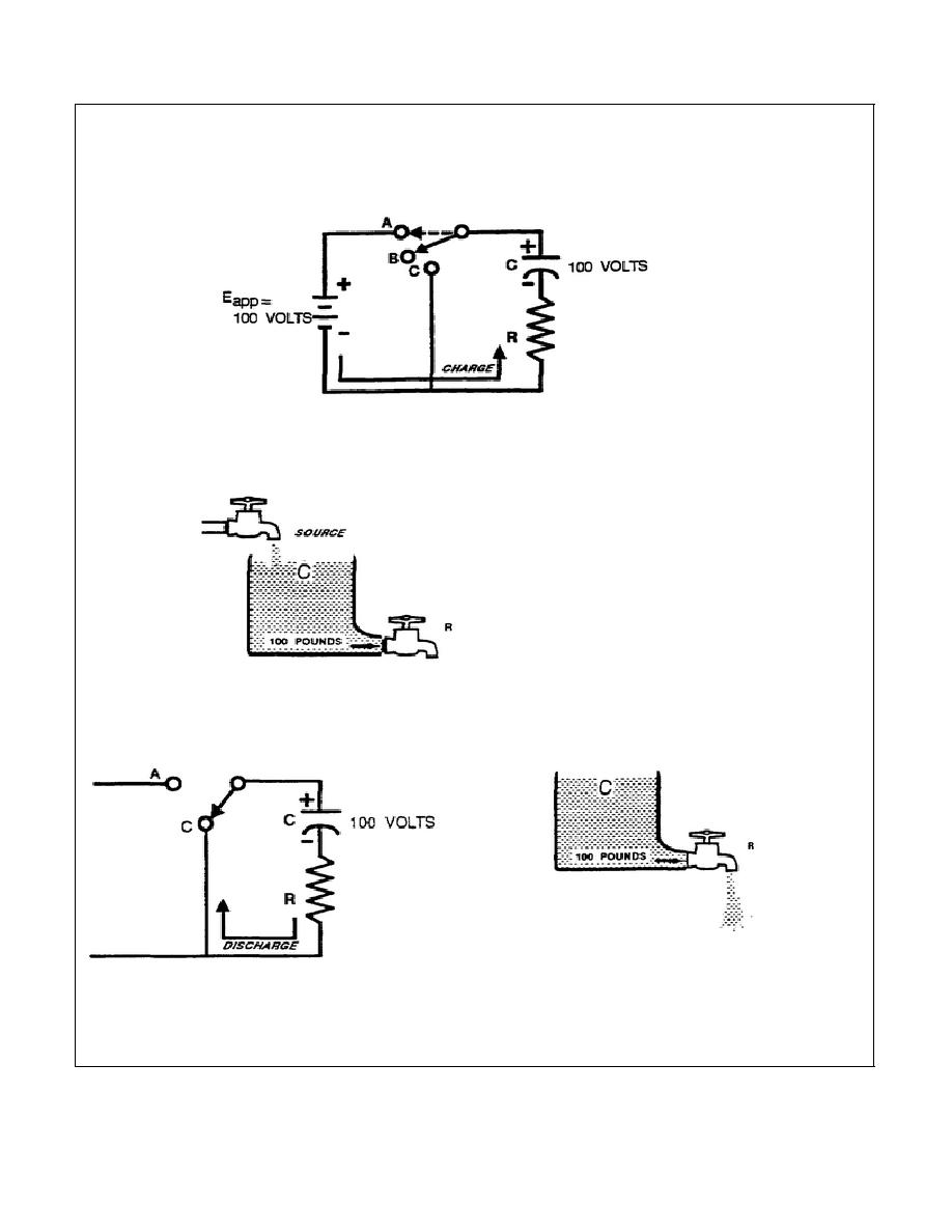
In a series RC circuit connected across a 100-volt DC source (sw. Pos. A), C will charge to 100 volts (in 10
RC time). Fig. 9.
Figure 9.
Remove the source voltage (sw. Pos. B), and C will remain at 100 V until a discharge path is provided.
This can be compared to filling a water tank (representing the capacitor) to a capacity of 100 lbs. of water, with
the drain valve closed, and then shutting off the source (fig. 9A).
Figure 9A
The water level in the tank (C) remains at 100 lbs of pressure, since there is no outlet (discharge path).
Placing the switch in Pos. C (fig. 9B), provides a discharge path for C.
Figure 9C.
Figure 9B.
This can be compared to opening the valve (fig. 9C) and letting the water start to drain out. (The valve represents
R in an RC circuit.)
1-25
IT0351


 Previous Page
