18.
(Continued)
In the figure on page 1-9, the truth table and the circuit for the NOT function are shown.
The requirement of a NOT circuit is that the output must be the complement of the input.
Thus, when switch A is closed (1), the relay opens the circuit to the load. When switch A
is open (0), the relay completes the circuit to the load.
The NOT function is indicated by a
over the
.
vinculum
19.
The logic of an OR function states:
variable
a. If any condition or all conditions are true, the result is true.
b. If any condition or all conditions are false, the result is true.
c. If any condition or all conditions are true, the result is false.
d. If any condition or all conditions are false, the result is false.
a.
20.
In any digital-computer equipment, there are many switching networks. In order to
analyze the circuit operation, it is often necessary to refer to these circuits without looking
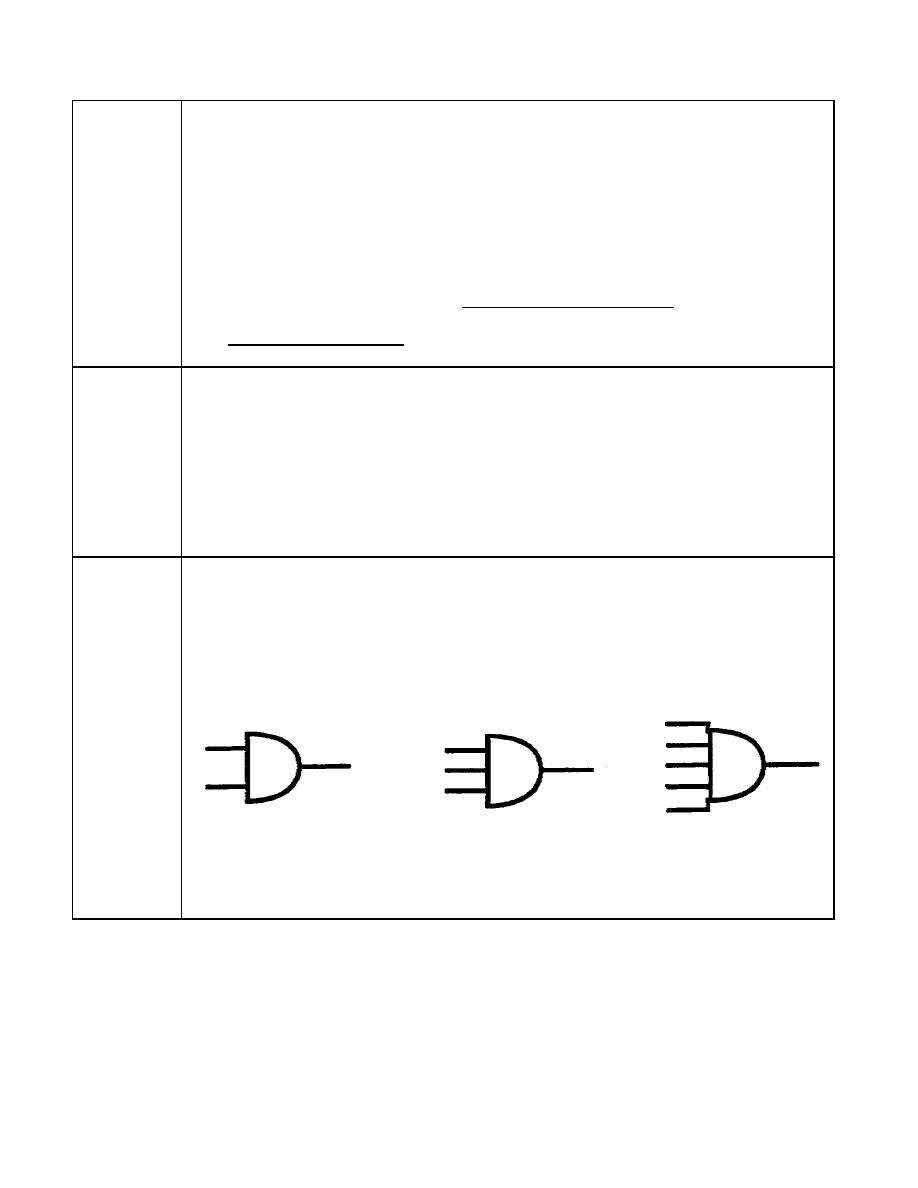
at their switching arrangements. This is done by the use of logic diagrams. Logic
diagrams for the AND operation are shown below.
1-11
IT0342


 Previous Page
