32.
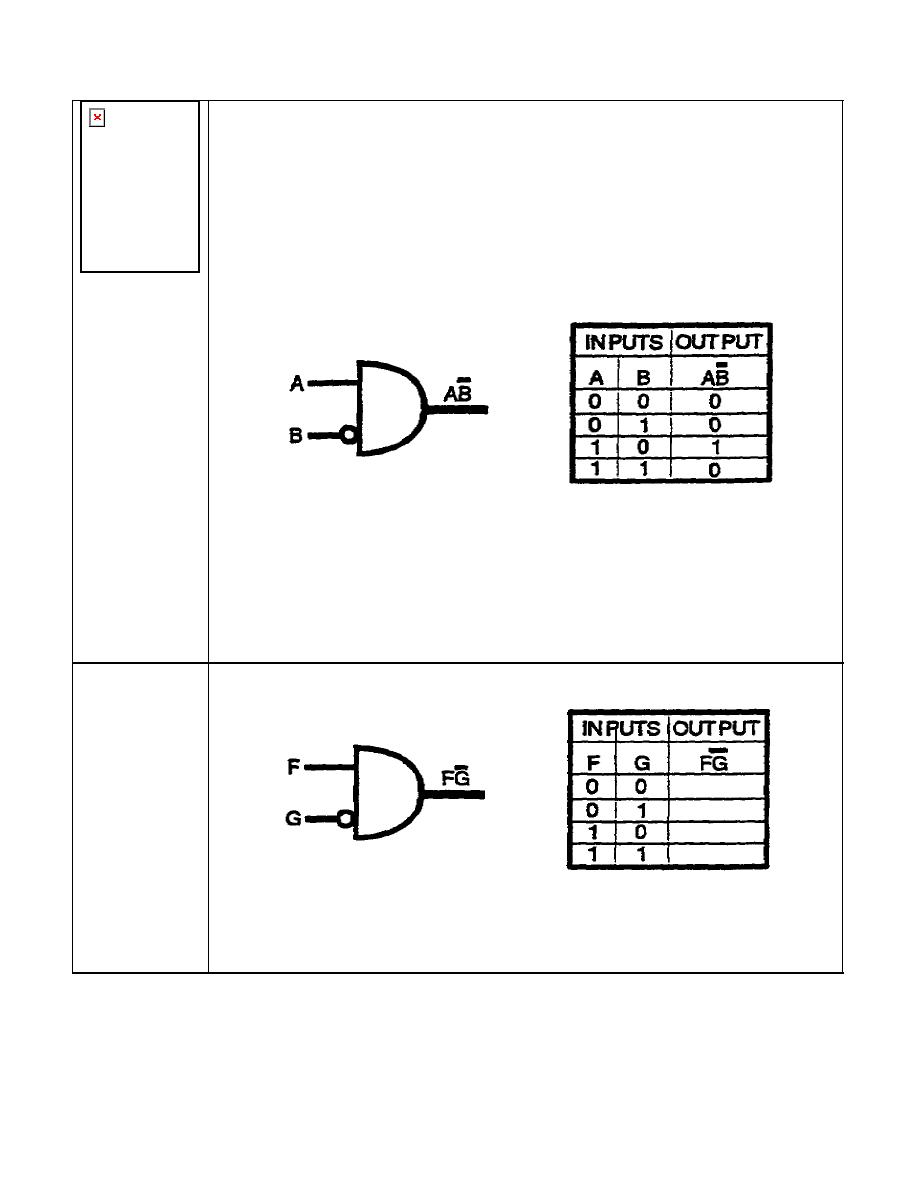
An INHIBITOR circuit is a combination of an AND gate and a NOT circuit in which
the NOT circuit is inserted between one input terminal and the AND gate.
An
INHIBITOR circuit performs the same logic as the basic AND gate with the exception
that one input is inverted at the inhibitor circuit.
Refer to the logic diagram and truth table above. Input B is the inhibited input. A 1
output is obtained only when a 1 is applied to input A and 0 is applied to input B. The
same logic would be obtained if input A were the inhibited input, only reversed.
Complete the truth below for the two-input INHIBITOR operation.
IT0342
1-20


 Previous Page
