4. SN+O+W
7.
5. second
6. VR+C
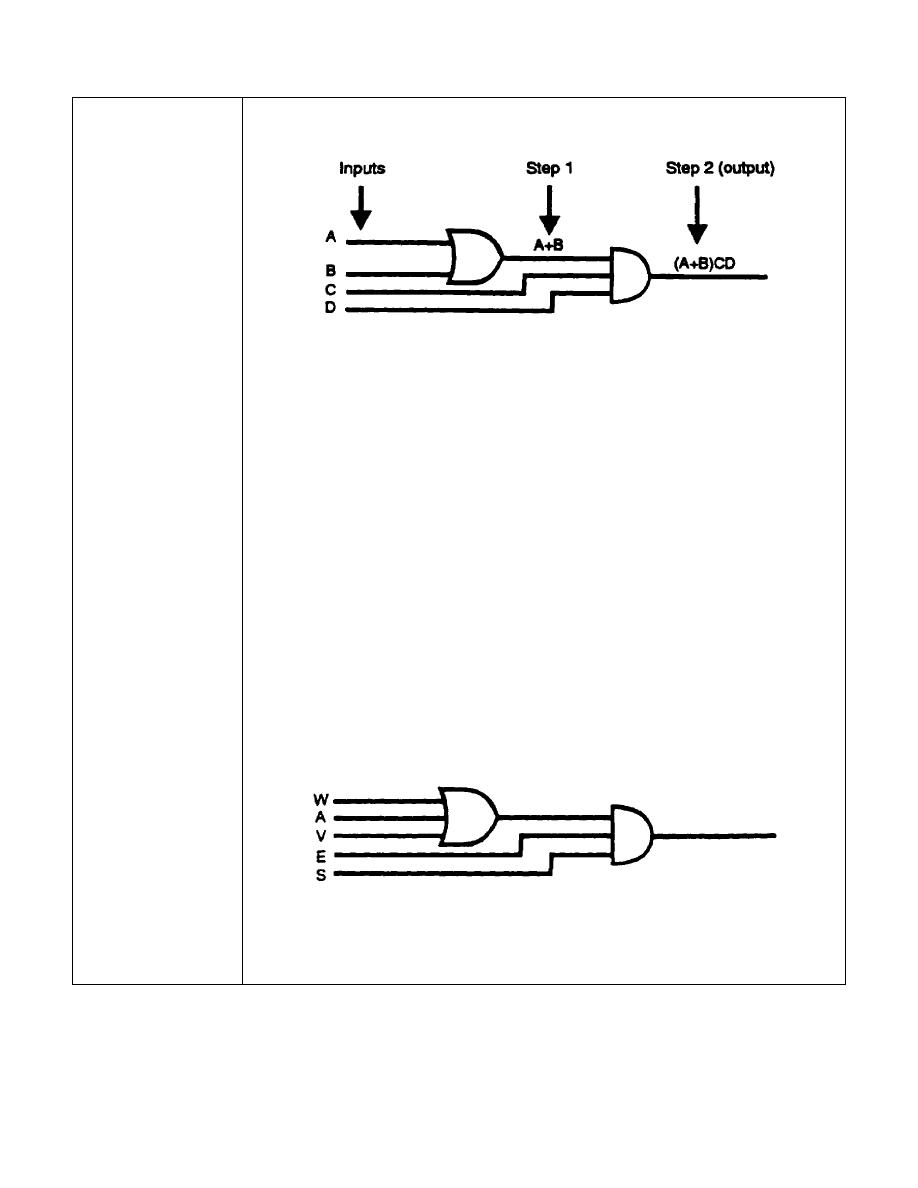
The diagram above is an example of second-order logic, an OR
circuit supplying an AND circuit. The output of each logic symbol
must be determined in order to develop an output Boolean
expression correctly. Start with the inputs to the first symbol and
proceed to the final output as indicated. Use the output of each
logic symbol as an input to the next symbol. Notice that the output
A+B of the OR gate (step 1) is put in parentheses in the final
output Boolean expression. It is enclosed in parentheses to
indicate that the complete quantity (A+B) is ANDed with CD.
Write the output Boolean expression for the second-order-logic
diagram below consisting of an OR circuit supplying an AND
circuit.
IT 0343
1-8


 Previous Page
