8. second
12.
9. (H+E) LP
10. second
11. SWA+B+K
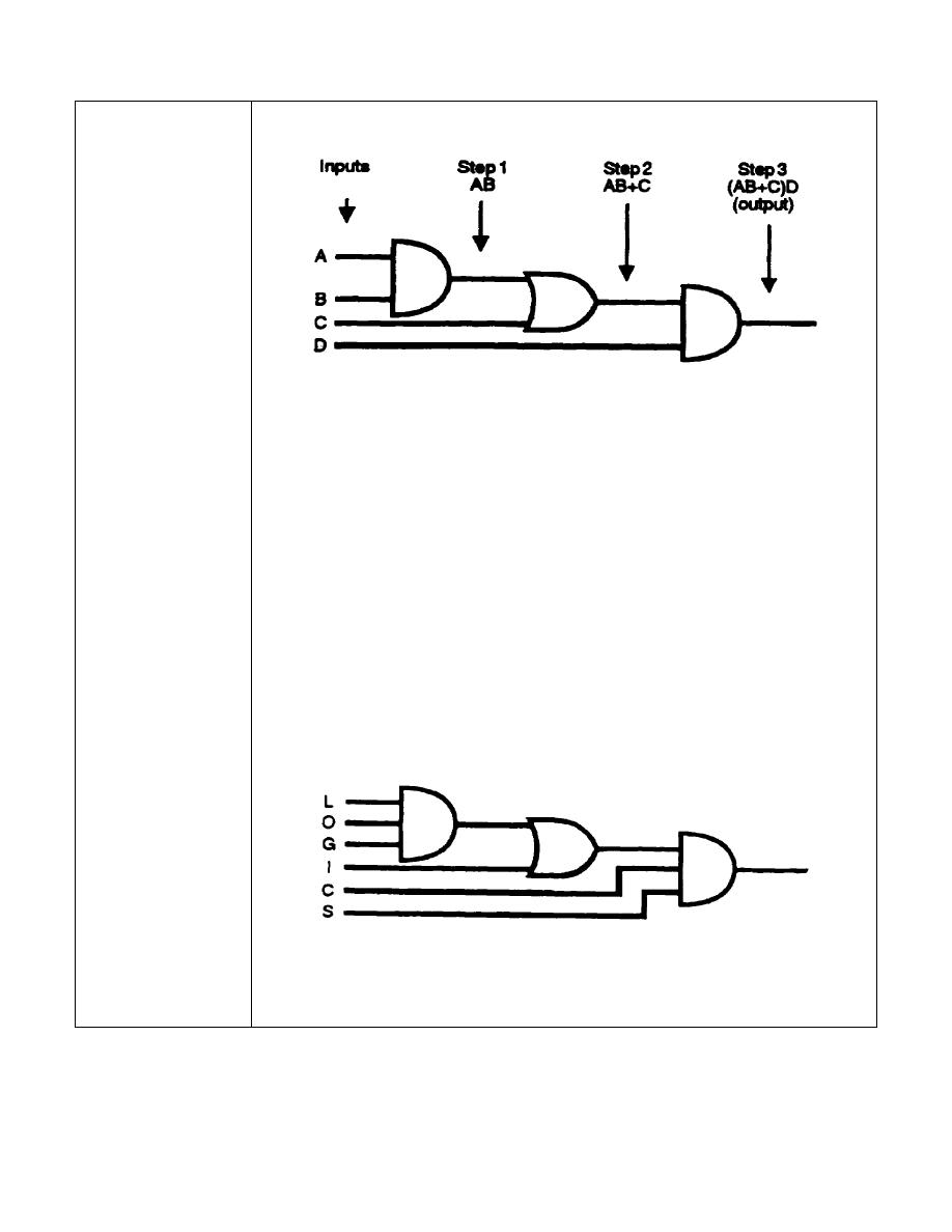
A third-order-logic diagram consisting of two AND gates and one
OR gate is illustrated above. The logic diagram can be converted
to a Boolean expression by using the same procedure of
determining the output of each symbol and working systematically
to the final output. Note that proper identity and separation are
maintained by using parentheses. If the parentheses had not
been used, the output Boolean expression would not have been a
correct indication of the logic diagram.
Write the output Boolean expression for the third-order-logic
diagram below containing two AND gates and one OR gate.
IT 0343
1-10


 Previous Page
