21.
The logic diagram in frame 20 is an example of
order logic.
18 [(C+O+M)PU+T]ER
22.
19a. HJ
b. HJ+K
c. (HJ+K) LM
d. (HJ+K) LM+N
20. [(A+B)E+C]RY
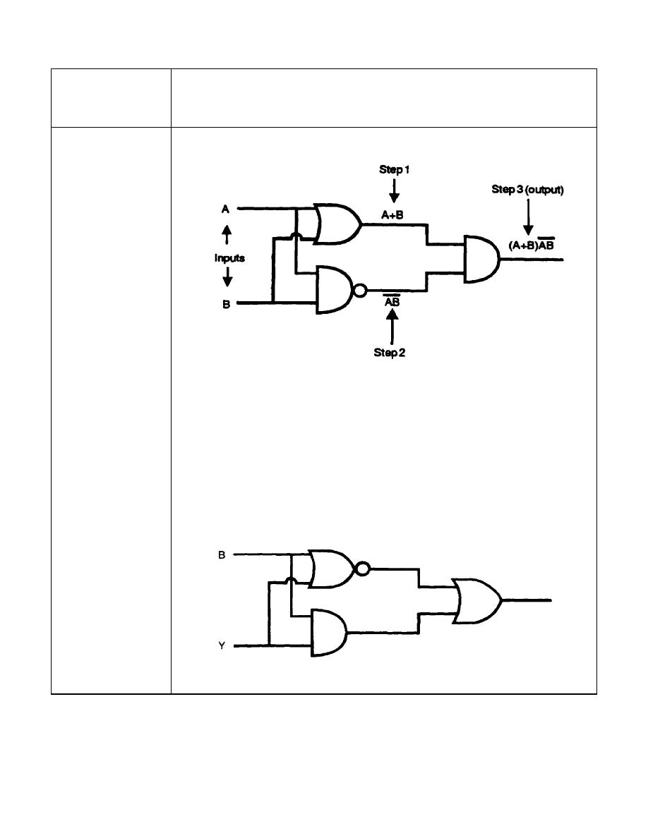
An output Boolean expression is obtained from the logic
diagram above in the same manner as the other diagrams
previously discussed. An output Boolean expression can be
systematically achieved by starting from the inputs and labeling
the output of each symbol as indicated.
Write the output Boolean expression for the logic diagram
below containing an AND gate, an OR gate, and a NOR gate.
1-15
IT 0343


 Previous Page
