8.
(Continued)
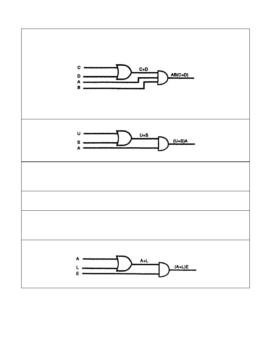
Step 3. Connect the output of the OR gate (step 2) to the input of the AND gate (step 1).
The completed logic diagram is shown below.
Convert the Boolean expression below to a logic diagram.
(U+S) A
SOLUTION:
9.
The Boolean expression (A + L) E represents a ____________ - input ____________
gate.
Two
AND
10.
Convert the Boolean expression below to a logic diagram.
(A + L) E
SOLUTION:
2-11
IT 0343


 Previous Page
