11.
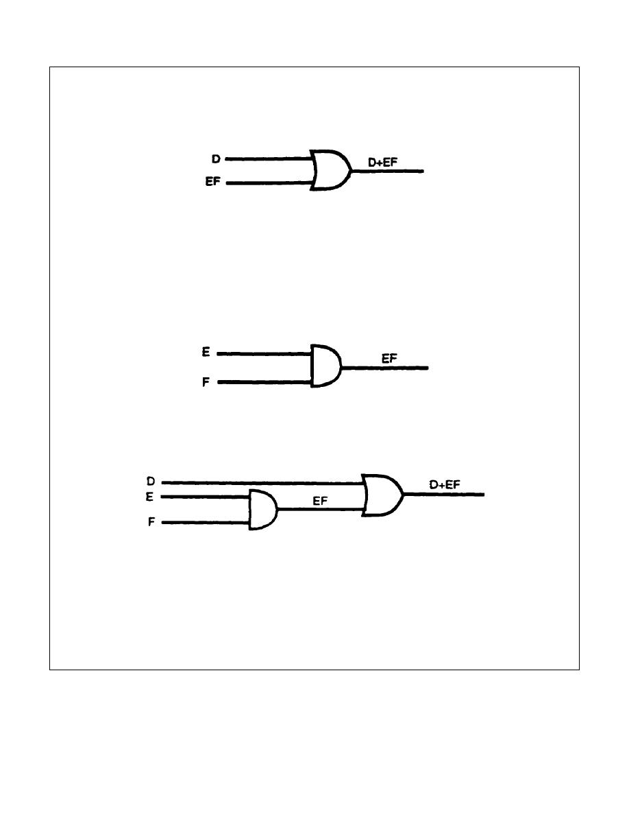
To convert the Boolean expression D+EF to a logic diagram, it is first necessary to identify
the overall circuit as an OR gate (+) with two inputs, D and EF. Input D is separated from
input EF by drawing the OR-logic symbol as illustrated below.
The output expression must be separated until only single-letter inputs- remain. When
letters are grouped together, as in the example D+EF, the groups must first be separated
from other groups or letters. This is accomplished as illustrated in the figure above: input
D is separated from input EF. Now, input EF must be identified and put into proper logic-
diagram form. EF by itself is identified as an AND gate with two inputs, E and F. Input E is
separated from input F by drawing the AND-logic symbol as shown below.
NOTE: Only single-letter inputs remain.
The two symbols are combined to represent the original Boolean expression D+EF by
drawing the output of the AND gate as one input (EF) to the OR gate as shown below.
Convert the Boolean expression below to a logic diagram.
EAS+Y
IT 0343
2-12


 Previous Page
