before there were enough transmitters to make direction finding worthwhile, A loop antenna
consists of one or more turns of conductor, either self supporting or wound on a frame. The
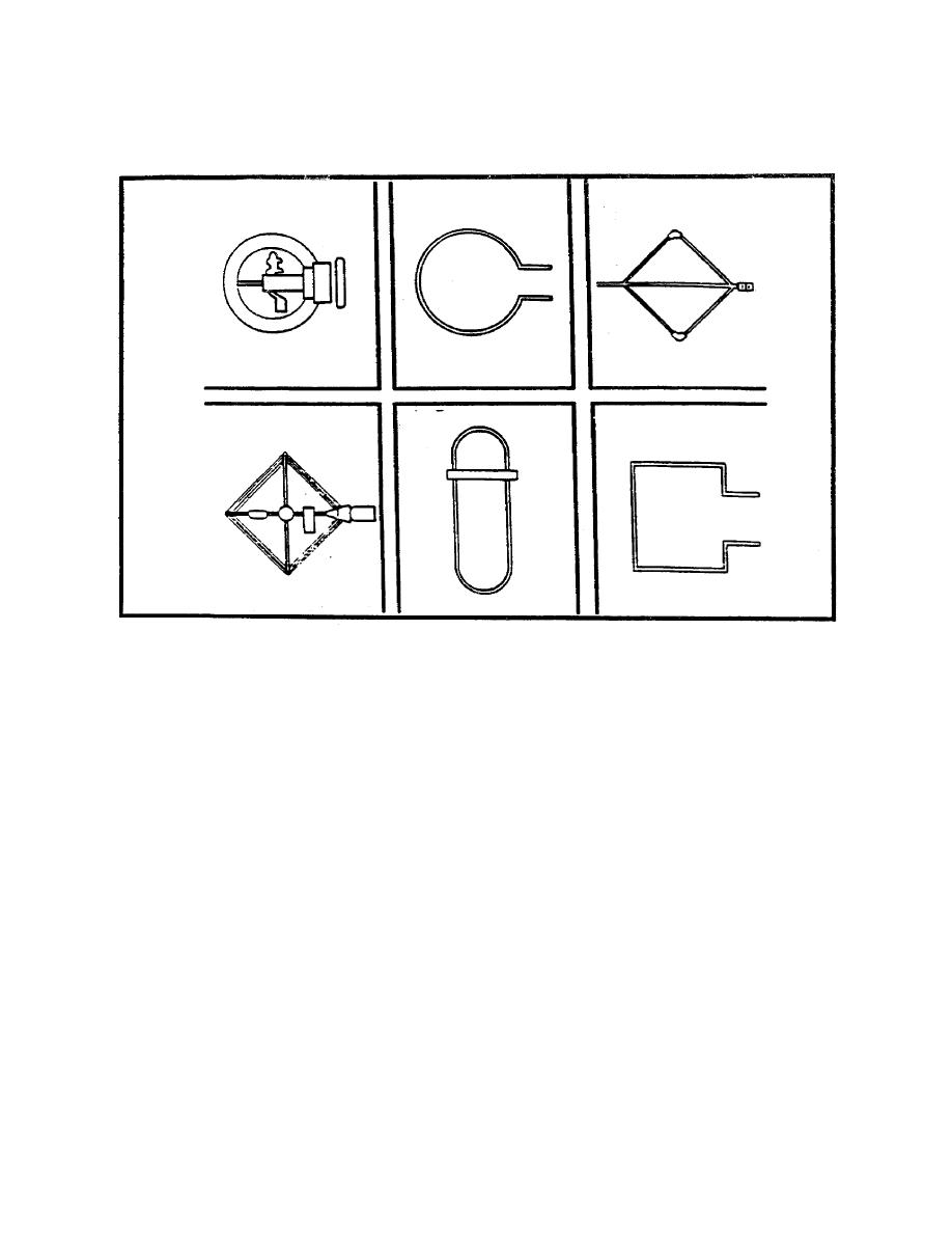
most common are diamond, square or circular loops (Figure 2-10).
Figure 2-10. Variation of Loop Antennas.
Imagine a loop placed in the path of a vertically polarized wave and turned so that a line from
side to side of the loop is parallel (plane perpendicular to the wave front) to the direction of
the wave. (Refer to Figure 2-3). Since polarization is discussed in terms of the electric field,
the magnetic field of a vertically polarized wave is horizontal. This horizontal magnetic field
induces voltage in the loop's vertical arms and in the horizontal arms, since the wave travels
parallel to them. The two voltages induced into the vertical arms tend to partially cancel
across the antenna, but only partially, since the simultaneous voltages are different. This
causes a voltage according to the size of the wave, or put more technically, a voltage is
developed which has a magnitude relative to the field intensity of the wave. If the loop is
rotated until it is broadside (plane parallel to the wave front) to the oncoming wave the
voltages induced in the arms are equal and in phase with each other and cancel across the
coupler to give a minimum response, or null. Two null points are present in a loop, 180
degrees apart, giving the antenna a response pattern shaped like a figure eight. (See Figure
2-11).
Unless the general direction of the transmitter is known, a direction finder equipped with a
single loop cannot determine whether the transmitter lies forward or to the rear of the
direction finder. There is no indication as to which of the two nulls indicates the true
direction. From the previous lesson you may remember that this is known as the
BIDIRECTIONAL AMBIGUITY, and solving the problem is known as resolving the bidirectional
ambiguity. A sense antenna,


 Previous Page
