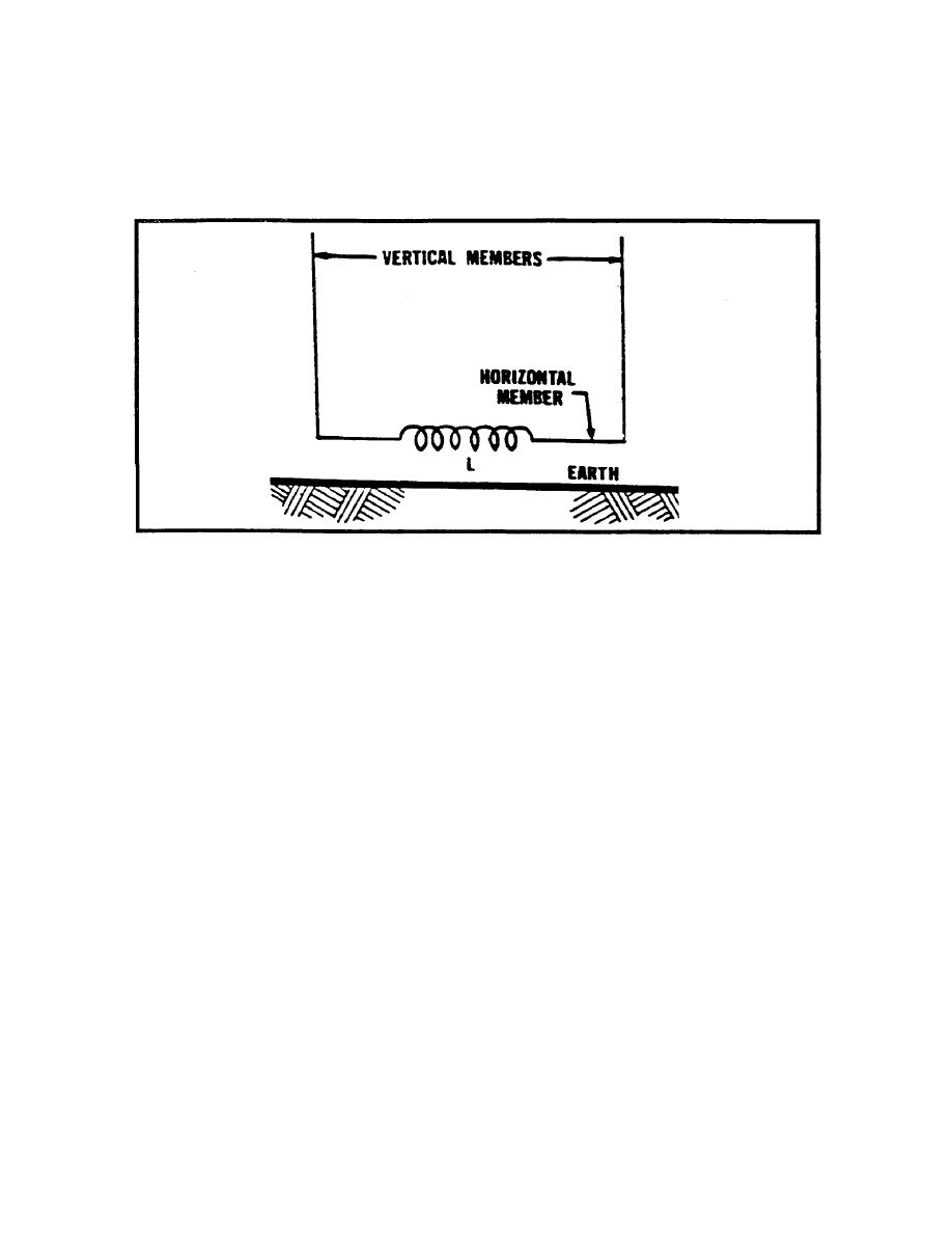
members effectively cancels the voltage induced in them. The response pattern is the same
figure eight as the loop antenna.
Both the loop and Adcock antenna have polarization errors when the incoming wave is
horizontally polarized, but so long as the vertical polarization is predominant the Adcock is
Figure 2-12. Example of adcock antenna.
relatively free from polarization error. The Adcock antenna also requires a sense antenna to
resolve the bidirectional ambiguity.
The crossed Adcock antenna consists of two identical Adcock antennas oriented 90 degrees
apart in azimuth. At low or medium frequencies crossed Adcock antennas can be made much
larger than rotatable Adcocks and are, therefore, much more sensitive. At high frequencies
this advantage is small because of the limitations imposed by spacing (OCTANTAL ERROR).
In a crossed Adcock system the maximum spacing is 1/2 wavelength between antennas (.707
wave length between diagonally spaced antennas). Above this limit the same indication may
be obtained for signals coming from three different directions. (Six before sensing). Above
approximately half this absolute limit the correction of octantal errors is necessary for almost
every azimuth reading taken, and the nominal top frequency is usually set at this point.
Circularly disposed antenna arrays (CDAA) are the largest installations sometimes several
areas in size requiring special coupling and sensing devices in order to present a directional
pattern on a visual display system. (Refer to Figure 2-9) While the systems are both accurate
and sensitive, direction finding is not their primary purpose.
Interferometric systems are a completely different class of direction finding systems (as
illustrated in Figure 2-13). The azimuth of an incoming wave is not deduced by rotating
beams. It is taken from the phase measurements of signals, made on a number of spaced
antennas. Unlike the beam-forming type of WADFs, interferometers accept all signals on the
IT0302
2-12


 Previous Page
