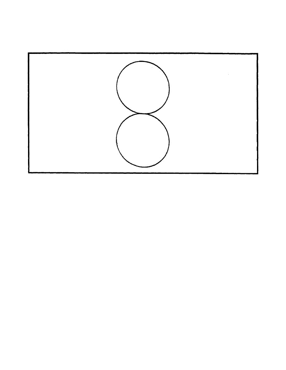
usually a whip, is placed at the center axis of the loop, and the two response patterns are
electrically combined to produce an unbalanced pattern (cardioid, or heart-shaped) which
can be used to resolve the bidirectional ambiguity.
Figure 2-11. Two null points.
The crossed loop antenna consists of two loops with identical characteristics mounted at
right angles to each other. Each loop has a figure eight pattern, but the two patterns are
displaced 90 degrees in azimuth. As a result, the ratio of the two responses varies with
direction. The outputs of the two antennas are connected through a coupler which can be
rotated to find the null. This coupler is called a goniometer or a rotary coupler. Since the
loops themselves are not rotated they can be made quite large for increased sensitivity.
Loop and crossed loop antennas are subject to large polarization errors.
An adcock antenna consists of two spaced vertical antennas connected in opposition (one to
each side of a coil). An example of a common type of Adcock is shown in Figure 2-12. In
theory it responds only to the vertically polarized wave and, therefore, is not subject to
polarization error. In practice there is some polarization error, but usually much less than In a
loop receiving the same signal. The Adcock is preferable when medium or high frequency
signals must be received at a point beyond ground wave range.
The action of the antenna, as far as vertically polarized waves are concerned, is identical with
that of the loop. A resultant current in the output coil is proportional to the difference of the
voltages induced in the vertical members, exactly as in the loop. Horizontally polarized
components of the incoming signals do not affect the antenna because of the absence of
upper and lower horizontal members and because the crossed arrangement of the center
2-11
IT0302


 Previous Page
