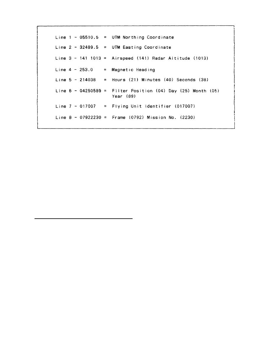
Figure 2-2. IR Data Block.
a.
Extracting the universal transverse mercator (UTM) coordinates from the data block
is simple. Refer to Figure 2-2. Read the first three digits of line 2 (324). Then, read the first
three digits of line 1 (055); this will give you the six-digit UTM coordinate 324055.
b.
In determining the location on the imagery, proceed in the Following manner:
Step 1:
Locate the center of the imagery just above the data block.
Step 2:
Mark off 7 inches opposite the aircraft's flight direction. You are now in the
general vicinity of the desired UTM coordinate.
4. Plotting peculiarities of the AN/AAS-24 IR mapping system and the AN/AAD-5 IR
reconnaissance set. The imagery produced by these IR systems is a continuous strip which is
normally presented by two parallel lines. There are a few peculiarities of IR imagery you
should be aware of:
a.
Altitude change. A change in the altitude of the aircraft will effect the size of the
area coverage.
(1) An increase in the altitude of the aircraft will cause the sensor to cover more
area on the ground and result in an increase in the width of your plot (Figure 2-3).
IT0654
40


 Previous Page
